Project
ATtiny85 Powered High Voltage AVR Programmer
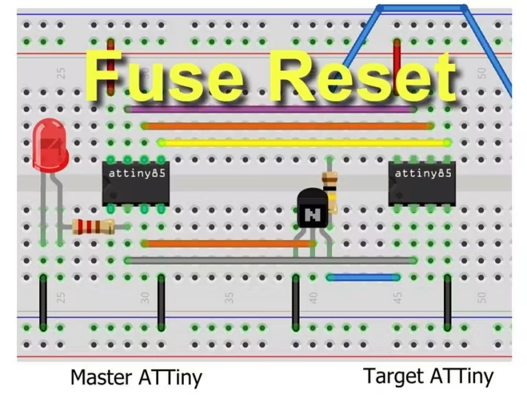
Build Notes
This very simple and inexpensive circuit will reset the fuses on a bricked ATtiny chip. Once programmed, no Arduino is required!
Story
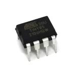
This simple and inexpensive high voltage AVR programmer for ATtiny chips requires only an ATtiny85 and a few components to build. Using Wayne Holder’s excellent ATtiny Fuse Reset posts as a starting point, this little device is able to reset the fuses on many ATtiny devices. With the correct (8-pin or 14-pin) wiring, it should be able to reset ATtiny13, 24, 25, 44, 45, 84, and 85 chips.
The fuse reset process requires a 12v reset signal and 5v to power the chip being reset. Wayne’s projects use a 5v power source, and either a separate 12v battery or an Arduino powered charge pump as the 12v source. To keep things simple, this project starts with a 12v power source and uses a 5v voltage regulator to provide 5v to power the ATtiny chips.
Using the Programmer
Hold the momentary switch down for a second or so. In most cases, the LED will light up very briefly (programming mode) and then turn off to indicate the reset has completed successfully.
Error Indications
If the LED stays on or begins flashing slowly, this indicates that the programmer could not read the signature of the target chip. Check the connections, and make sure both chips are plugged in completely and in the correct orientation.
If the LED flashes quickly, this indicates that the fuse reset failed – the programmer recognized the device signature and attempted to reset the fuses, but the fuse values read from the device after the reset were not as expected. In my experience, this is pretty rare.
How to Make
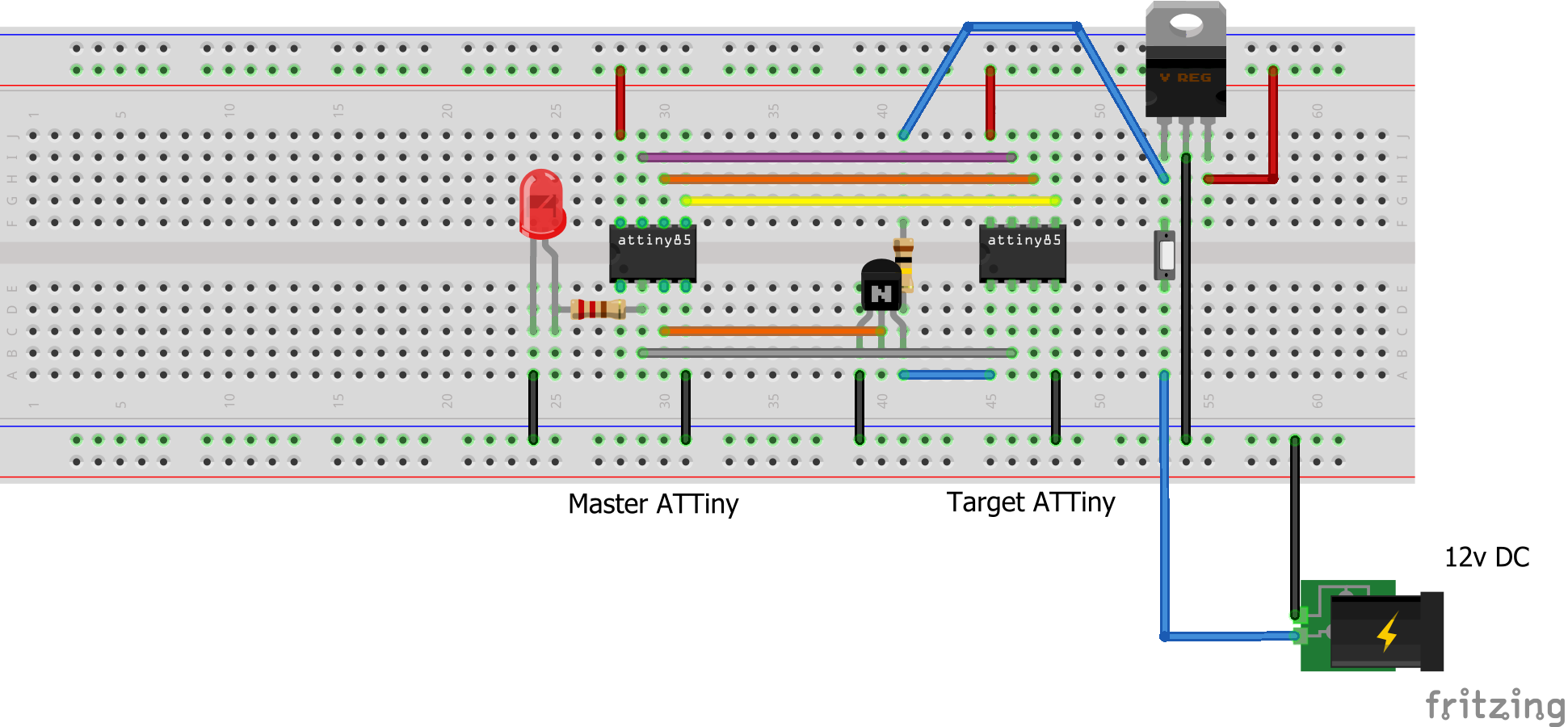
The circuit is so simple that it can be breadboarded in a matter of minutes. You’ll need to use an Arduino (Arduino as AVR) to load the sketch into the master ATtiny85. This must be done only once; the master chip can then be used to reset the fuses on an unlimited number of target devices.
Connections
8-pin
// pasMaster	Target (8-pin)
2	2
4 GND	4 GND
5	5
6	6
7	7
8 5v	8 5vte your code here
14-pin
// paste your code hereMaster	Target (14-pin)
2	2
4 GND	11, 12, 13, 14 GND
5	7
6	8
7	9
8 5v	1 5v
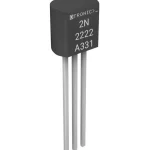
In both cases, Master pin 3 goes to the base of the NPN transistor. The emitter goes to ground, and the collector goes to pin 1 of the target chip. The collector is also connected to 12v through the 1KΩ resistor.
Master pin 2 is also connected (through a 330Ω resistor) to the status LED.
Note: To keep the circuit simple, the capacitors normally surrounding the voltage regulator have been omitted. In most cases, the circuit will work fine (especially with the 7805 regulator). If you experience stability problems, a 10µF and 0.1µF capacitor connecting the input and output (respectively) to ground might be necessary.
Schematics
Fuse Resetter for 8-pin chips
This circuit resets the 8-pin ATTiny chips. Schematic for the 14-pin version is below.
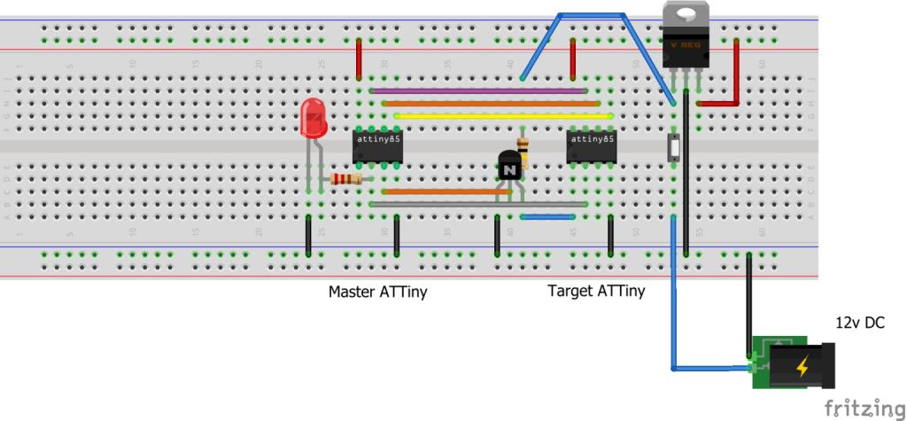
8-pin Schematic
This circuit is for the 8-pin ATTiny chips. Schematic for the 14-pin chips is below.
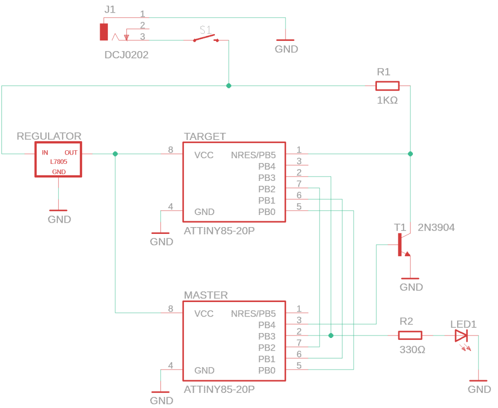
14-pin Schematic
This circuit is for resetting the 14-pin ATTiny chips.
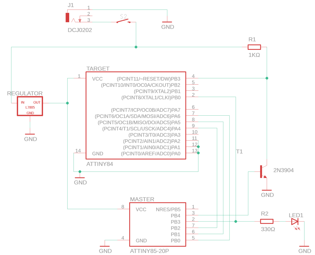
Code
ATTiny85 Powered High Voltage AVR Programmer
C/C++
Load this sketch onto the “Master” ATTiny85. It can then be used to reset the fuses on many ATTiny chips.
// AVR High-voltage Serial Fuse Reprogrammer
// Adapted from code and design by Paul Willoughby 03/20/2010
//   http://www.rickety.us/2010/03/arduino-avr-high-voltage-serial-programmer/
// and Wayne Holder
//   https://sites.google.com/site/wayneholder/attiny-fuse-reset
//
// Fuse Calc:
//   http://www.engbedded.com/fusecalc/

#define  LED      3    // Status indicator LED
#define  RST      4    // (13) Output to level shifter for !RESET from transistor
#define  SCI      3    // (12) Target Clock Input
#define  SDO      2    // (11) Target Data Output
#define  SII      1    // (10) Target Instruction Input
#define  SDI      0    // ( 9) Target Data Input

#define  HFUSE  0x747C
#define  LFUSE  0x646C
#define  EFUSE  0x666E

// ATTiny series signatures
#define  ATTINY13   0x9007  // L: 0x6A, H: 0xFF             8 pin
#define  ATTINY24   0x910B  // L: 0x62, H: 0xDF, E: 0xFF   14 pin
#define  ATTINY25   0x9108  // L: 0x62, H: 0xDF, E: 0xFF    8 pin
#define  ATTINY44   0x9207  // L: 0x62, H: 0xDF, E: 0xFFF  14 pin
#define  ATTINY45   0x9206  // L: 0x62, H: 0xDF, E: 0xFF    8 pin
#define  ATTINY84   0x930C  // L: 0x62, H: 0xDF, E: 0xFFF  14 pin
#define  ATTINY85   0x930B  // L: 0x62, H: 0xDF, E: 0xFF    8 pin

int error = 0;
byte FuseH = 0;
byte FuseL = 0;
byte FuseX = 0;

void setup() {
  pinMode(RST, OUTPUT);
  digitalWrite(RST, HIGH);  // Level shifter is inverting, this shuts off 12V
  pinMode(SDI, OUTPUT);
  pinMode(SII, OUTPUT);
  pinMode(SCI, OUTPUT);
  pinMode(SDO, OUTPUT);     // Configured as input when in programming mode

  digitalWrite(SDI, LOW);
  digitalWrite(SII, LOW);
  digitalWrite(SDO, LOW);

  delayMicroseconds(30);  // wait long enough for target chip to see rising edge
  digitalWrite(RST, LOW);  // 12v On
  delayMicroseconds(10);
  pinMode(SDO, INPUT);      // Set SDO to input
  delayMicroseconds(300);
  unsigned int sig = readSignature();

  if (sig == ATTINY13) {
    writeFuse(LFUSE, 0x6A);
    writeFuse(HFUSE, 0xFF);
    readFuses();    // check to make sure fuses were set properly
    if (FuseL != 0x6A || FuseH != 0xFF) {
      error = 5;    // fast flash if fuses don't match expected
    }
  } else if (sig == ATTINY24 || sig == ATTINY44 || sig == ATTINY84 ||
             sig == ATTINY25 || sig == ATTINY45 || sig == ATTINY85) {
    writeFuse(LFUSE, 0x62);
    writeFuse(HFUSE, 0xDF);
    writeFuse(EFUSE, 0xFF);
    readFuses();    // check to make sure fuses were set properly
    if (FuseL != 0x62 || FuseH != 0xDF || FuseX != 0xFF) {
      error = 5;    // fast flash if fuses don't match expected
    }
  } else {
    error = 1;      // slow flash if device signature is invalid
  }

  digitalWrite(SCI, LOW);
  digitalWrite(RST, HIGH);   // 12v Off
  digitalWrite(LED, LOW);    // LED off for succerss
}

void loop() {
  // Flash LED if there was an error
  while (error > 0) {
    int d = 500 / error;
    digitalWrite(LED, HIGH);
    delay(d);
    digitalWrite(LED, LOW);
    delay(d);
  }
}

byte shiftOut (byte val1, byte val2) {
  int inBits = 0;
  //Wait until SDO goes high
  while (!digitalRead(SDO))
    ;
  unsigned int dout = (unsigned int) val1 << 2;
  unsigned int iout = (unsigned int) val2 << 2;
  for (int ii = 10; ii >= 0; ii--)  {
    digitalWrite(SDI, !!(dout & (1 << ii)));
    digitalWrite(SII, !!(iout & (1 << ii)));
    inBits <<= 1;
    inBits |= digitalRead(SDO);
    digitalWrite(SCI, HIGH);
    digitalWrite(SCI, LOW);
  }
  return inBits >> 2;
}

void writeFuse (unsigned int fuse, byte val) {
  shiftOut(0x40, 0x4C);
  shiftOut( val, 0x2C);
  shiftOut(0x00, (byte) (fuse >> 8));
  shiftOut(0x00, (byte) fuse);
}

void readFuses () {
  shiftOut(0x04, 0x4C);  // LFuse
  shiftOut(0x00, 0x68);
  FuseL = shiftOut(0x00, 0x6C);

  shiftOut(0x04, 0x4C);  // HFuse
  shiftOut(0x00, 0x7A);
  FuseH = shiftOut(0x00, 0x7E);

  shiftOut(0x04, 0x4C);  // EFuse
  shiftOut(0x00, 0x6A);
  FuseX = shiftOut(0x00, 0x6E);
}

unsigned int readSignature () {
  unsigned int sig = 0;
  byte val;
  for (int ii = 1; ii < 3; ii++) {
    shiftOut(0x08, 0x4C);
    shiftOut(  ii, 0x0C);
    shiftOut(0x00, 0x68);
    val = shiftOut(0x00, 0x6C);
    sig = (sig << 8) + val;
  }
  return sig;
}
Credits

sbinder
https://www.hackster.io/sbinder/attiny85-powered-high-voltage-avr-programmer-3324e1
Parts List