Project
ATtiny85 Programming Shield for Arduino UNO
Build Notes
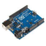
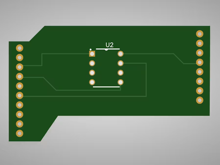
An arduino uno shield for rapid attiny programming
Story
Attiny85 Programmer Shield for Arduino UNO
An Arduino UNO shield for Attiny85 Programming.
Programming ATtiny boards can be a tiring labor, so make it faster and easier with this shield!
Step 1: Add Support for the ATtiny85 to the Arduino URL Board Manager
By default the Arduino IDE does not support the ATtiny85 so it’s required to add support for the Attiny85 to the Arduino Board Manager:
From the Arduino IDE Go to Arduino->Preferences then scroll down to Additional Board Managers URLs
Copy & paste the following (if you already have a board manager URL just add a comma before pasting)
Press “OK” at the bottom then restart the Arduino IDE
Step 2: Install the ATtiny Board Package From the Arduino IDE go to Tools–> Board–>Boards Manager
A new tab will open and at the top of the tab type: attiny
Select Install on the Attiny by David. A Mellis
Restart the Arduino IDE
The ATtiny85 board should now be added ! Go to Tools–> Board–>Attiny85
Step 3: Set the Arduino Uno Into ISP Mode
Since what we want is to be able to program the ATtiny85 from the Arduino IDE which requires to burn the bootloader to the ATtiny85 we will need to “prep” the Arduino fist by uploading the ISP sketch to it.
In the Arduino IDE select File–>Examples–> 11. Arduino ISP–>ArduinoISP
the ISP sketch should open and upload it to your Arduino Uno
Step 4: How a Microcontrollers Pins Are Labeled
Before the connections are made there is a very important fact to know how pins on microcrontrollers/ICs are labeled.
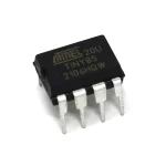
Pin numbers used to program a chip on the Arduino IDE are based on how the chip manufacturer has internally named/aranged the pins. The manufacturer of the ATtiny85 is ATMEL (the AT in ATtiny85-actually stands for ATMEL);It’s common for chips to have the first two initials of the company who makes them.
Pins are gathered into groups called “ports” these ports are labeled A, B, C etc. Each port has a number of pins which are labeled 0, 1, 2, 3 etc and stick out on different parts of the chip which is why a microcontroller’s physical pin often time will be different than the pin number used when programming the chip.
An example:
Photo title
A short explanation of what this photo shows.
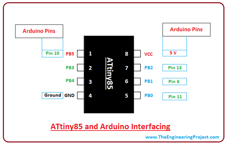
PB0 (in the above datasheet) just means pin 0 is located on Port B of the Chip.
If pin 0 was located on Port A the name would look something like PA0 (Port A pin 0)
To add to the complexity pins can have more than one fuction and be labeled multiple names.
Wrapping it all together! :
Writing a program to light an LED on pin 0 on the ATtiny85 might be confusing at first because just by looking at the chip, there is no pin 0! However, by checking the datasheet of the ATtiny85 from ATMEL-snippet shown above-pin 0 is internally located on the chip’s port B (and is actually the chip’s physical pin 5 )!
Step 6: Making the ATtiny85 Arduino Compatible
By default any fresh microcontroller chip bought will not be able to be programmed with the Arduino IDE out of the box. This is why it’s required to burn the Arduino bootloader onto the chip to make sure the chip will accept any programs uploaded via the Arduino IDE.
Quick checklist before pressing “burn bootloader”
Go to Tools -> Board scroll to the bottom select ATtiny25/45/85
Under Tools -> Processor–> 8 MHz (internal)
Under Tools–>Programmer–>Arduino as ISP
Check that all wiring, capacitor, and board selections are correct
Finally select Burn Bootloader
leave the wires connected they will be used in the next step
A message will appear saying “Done Burning Bootloader”
Step 7: Uploading the Blink Sketch
Test that the ATtiny85 can now receive sketches from the Arduino IDE by uploading the blink example
Go to File–>Example–>01.Basics–>blink
Edit the sketch by replacing pin 13 with 0
Make sure to still have the ATtiny85 board settings from the previous step selected
Make sure all wiring is the same as the previous step
Upload the sketch
Wire an LED by connecting the anode to pin 0 (physical pin 5 ) and the cathode to a 1K resistor connected to ground (physical pin 4)
While a resistor is not needed since the battery provides 3v (not enough to blow up an LED) it is recommended to lower the brightness of the LED.
Hope it helps on future projects!
Attiny Programming Shield
https://www.hackster.io/pcbway/products/custom-pcb?ref=project-e51476
Download or order the PCB from my project on pcbway!
https://www.pcbway.com/project/shareproject/Attiny85_Programmer_Shield_for_Arduino_UNO_170b5847.html
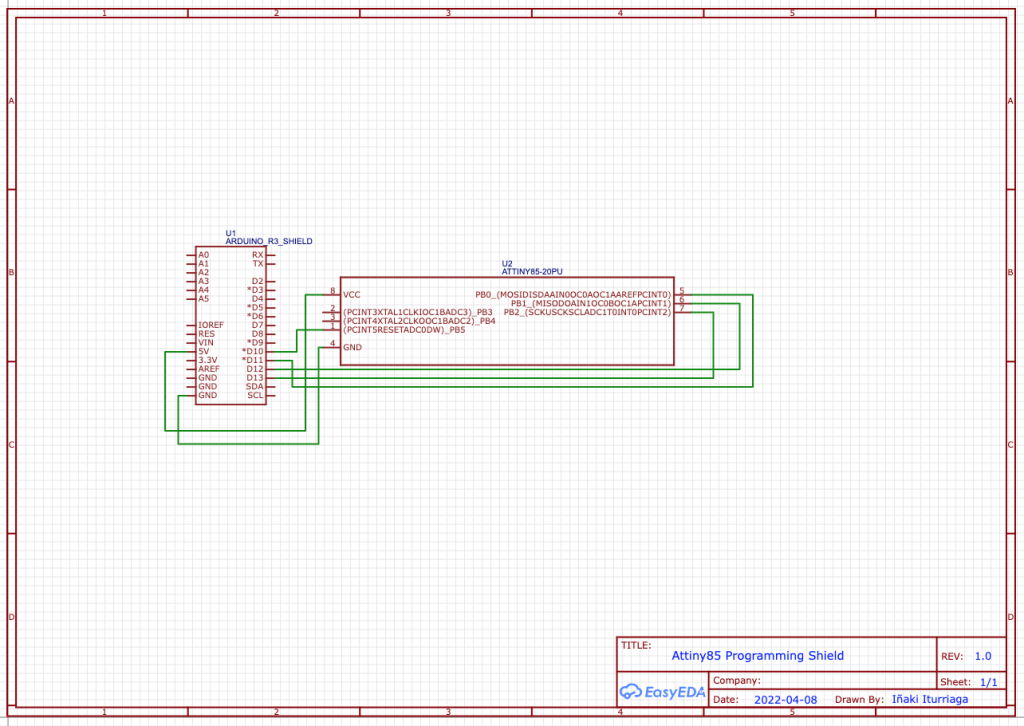
Schematics
Code
/*
  Blink

  Turns an LED on for one second, then off for one second, repeatedly.

  Most Arduinos have an on-board LED you can control. On the UNO, MEGA and ZERO
  it is attached to digital pin 13, on MKR1000 on pin 6. LED_BUILTIN is set to
  the correct LED pin independent of which board is used.
  If you want to know what pin the on-board LED is connected to on your Arduino
  model, check the Technical Specs of your board at:
  https://www.arduino.cc/en/Main/Products

  modified 8 May 2014
  by Scott Fitzgerald
  modified 2 Sep 2016
  by Arturo Guadalupi
  modified 8 Sep 2016
  by Colby Newman

  This example code is in the public domain.

  https://www.arduino.cc/en/Tutorial/BuiltInExamples/Blink
*/

// the setup function runs once when you press reset or power the board
void setup() {
  // initialize digital pin LED_BUILTIN as an output.
  pinMode(LED_BUILTIN, OUTPUT);
}

// the loop function runs over and over again forever
void loop() {
  digitalWrite(LED_BUILTIN, HIGH);   // turn the LED on (HIGH is the voltage level)
  delay(1000);                       // wait for a second
  digitalWrite(LED_BUILTIN, LOW);    // turn the LED off by making the voltage LOW
  delay(1000);                       // wait for a second
}
Credits
coloitu_
https://www.hackster.io/coloitu_/attiny85-programming-shield-for-arduino-uno-e51476
Parts List