Project
Getting Started With Forgix
Build Notes
How to get started with the Forgix FPGA and RP2354A
Things used in this project
Hardware components
 | Adiuvo Engineering & Training Forgix Development Boar |
Software apps and online services

Story
Introduction
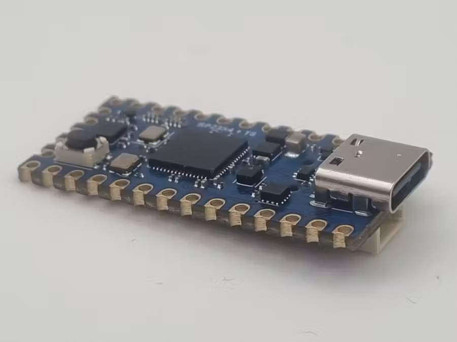
The Forgix board contains a combination of RP2354 and the Efinix T8 FPGA, powered and programmed over USB C in a compact footprint.
This makes for a compact and powerful FPGA development board which can be used for many projects which require parallel (FPGA) and sequential (RP2354) processing.
The Efinix FPGA is the T8 from the Trion range and provides the developer with 7384 Logic elements, 122.8 Kbits of embedded memory / 24 embedded memory blocks and 8 embedded multipliers.
The RP2354, takes the base design provided by the RP2350 and integrates 2 MB of QSPI flash into the package, this allows for a more compact solution. It retains the dual-core Arm Cortex-M33 and dual-core Hazard3 RISC-V architecture, 520 KB of SRAM, PIO blocks, and enhanced security features.
We develop the Efinix FPGA using the Efinity design software, while we can develop the RP2354 application in several different ways including C/C++ or MicroPython. In this instance we will be using MicroPython but we will be setting up the system to ensure we are able to develop using a C/C++ approach as too if desired later.
Architecture
The architecture of the Forgix board is straightforward and designed to provide the developer with straightforward access to the FPGA and RP 2354.
Users connect to the RP2354 over the USB C Interface, this RP2354 is then connected to the T8 FPGA by SPI and several dedicated GPIO. This SPI port is used for configuring the FPGA, but can be retained post configuration to control applications deployed into the FPGA.
Along with the FPGA and USB C the RP2354 is connected to the IO pins providing two UARTS. There is also a IIC QWIIC connector mounting available, this is fitted on the initial 100 production units, but is unfitted on the main production batch. This enables expansion with a range of IIC sensors and drives if desired.
The FPGA is connected to a push button switch, a tri colour LED, the RP 2354, and 11 IO on the board edge.
Clockwise the FPGA is clocked from a 32 MHz oscillator, while the reset can be provided by the RP2354 if desired.
Installing the Tools
To be able to work effectively with this board we need the following tools.
- Pico SDK installed via VS Code.
- Efinity FPGA development Software.
- RP Pico2 MicroPython UF2 Image.
- Thonny for application development.
Download and install the three applications, store the UF2 in a directory you can easily access as we will need this very soon.
To download and install the Efinity Development suite you will need to register with an email address.
Once the tools have been installed the next step in VSCode is to install the VSCode extension. This will install a set of tools called picotools and we will be able to use these tools in the development of our applications easing it significantly.

With the extension installed you will see a new icon on the left menu for RP2354 development. This will help you develop applications using C/C++/Zephyr/MicroPython and Rust.
ensure your path contains the location of the picotools normally under your user / account.

Setting the RP2354 into Boot Mode
The next step is to connect your Forgix board to your development machine using the USB C Cable.
Photo title
A short explanation of what this photo shows.

To be able to work with the Forgix board, we need to be able to load application software onto the RP2354.
the software we load on will be in a UF2 format which is the result of either compilation of a project or downloading a pre existing image.
By default the Forgix comes with a UF2 loaded which is available on the repo and works with a host python application to program the FPGA, the host application is also in the same repo. This makes the RP2354 act as a programmer, but not much more.
If we want to load on MicroPython like we do in this application.
What we want to do is replace the currently loaded UF2 with the MicroPython UF2. to do this we need to make the Forgix board enter boot mode.
To be able to do this we need to ensure the Forgix enters boot mode, over USB C.
When in boot mode we will see the Forgix mount as a drive on our host system which allows us to drag and drop the UF2. Shortly after we do this the RP2354 will reboot and start running the UF2.
To be able to enter boot mode we have two options

First is to hold the program pin low on the IO ring while power is applied, we can do this with a wire jumper. However, there is a more elegant way.

Alternatively we can use the picotools just installed and a command line, issuing the command.
picotool reboot -f - uIf this is successful, it depends on the SW you have loaded so it can fail (hence the method above too) you will see the drive mount on your system.
This is the better way to enter boot mode and should be followed unless you have messed up the SW application running on the board some how. Then use the method mentioned above.

We are now ready to start our development of an application for the FPGA.
RP2354 SW
Once the RP2354 has entered boot load and the MicroPython UF2 has been loaded.
The next step is to upload the generated files for the python application, these are split into a files which will manage the loading of the FPGA, and communication with the resultant design, these files can be reused across projects.
Along with these files are a main application which will communicate with the FPGA and perform the applications we have implemented.
There are two files.
- Forgix_basics.py
- Forgix_fpga.py
The lowest-level file is forgix_fpga.py. This is the reusable FPGA interface layer and is the file that handles the configuration pins, reset sequencing, CDONE checking, and the simple serial command interface used once the FPGA has configured. The idea here is that this file is not tied to a particular example, it is the common FPGA loader and communications layer that other designs can build on.
Above this sits forgix_basics.py. This file provides the application-level API for the demonstration designs. Rather than making the user directly issue register reads and writes, it wraps the basics design registers in simple Python calls. These calls allow the MicroPython application to set the RGB LED brightness and colour, read back the push button state, and update outputs.
One key point we found during testing is that the FPGA image itself should remain on the host PC, when working with MicroPython. This is as the storage space is limited and copying the large .bin or .hex file into the RP2354 MicroPython filesystem may cause problems due to its size.
To avoid this, the FPGA image is kept in the project outflow directory on the host machine, and the board is programmed using the mpremote mount flow.
There is a small loader script, called program_lab_from_mount.py, this runs on the RP2354 but reads the FPGA image through the mounted host directory. This gives us the convenience of MicroPython loading while avoiding the risk of filling or damaging the MicroPython filesystem.
Running this command will show the following, we will generate the FPGA file used later in the project.

Which bring us to an interesting point running python remotely on the RP2354.
To do this we use mpremote, which enables us to remotely interact with, manage the filesystem on, and automate a MicroPython device over a serial connection.
Exactly what we have on the Forgix board.
So when we run commands on our host machine such as
python scripts/program_fpga_from_mount.py --port COM11 --design buttonWe are actually running a command similar to
python -m mpremote connect COM11 mount C:\hdl_effinx\basics run drivers\micropython\program_button_from_mount.pyHowever, the python script we call on the host generates the correct commands to send over mpremote.
Once the FPGA is loaded we can then use a similar approach to test the application loaded into the FPGA and at the same time use the features of the RP2354 for the application if we desire.
FPGA Development
The next step is to create the FPGA designs, this needs to do the following.
- Sample the button
- Change colours of the RGB LED
- Generate a PWM for a servo
To do this we can use VHDL to write the module. However, we also need a file which will allow commands to be sent over the SPI network. This allows us to read and write the registers used to control / sample the above features.
The first thing we need to do in Efinity is open the tool

From the menu option select, create new project.

On the design tab we can add the files from the project repository and select the top level VHDL architecture name. We can also add in the constraints, there are two kinds used the SDF which defines timing and the ISF which defines the IO locations.

Once that is completed we can use the buttons along the top to synthesise, place and route the design and generate the bit stream.

The ISF format looks as below for the Forgix board, the pin mappings align with the schematic pin allocation.

Once the bit stream has been generated we can started testing with the Forgix board.
Testing
With the Forgix connected to the host machine over USB C, we can again use the mpremote to control the application we want to deploy on the board. All that is currently on the board is the forgix_fpga.py and the forgix_basics.py, the reset we can load on with the mpremote.
The beauty of doing this using mpremote, in this manner is the python file is downloaded and executed on the Forgix board. But nothing is left on the Forgix file system after the application finishes running.
Running the example application on the Forgix shows the following when running.

Before the button is pushed.

After the button is pushed

While pressing the button increases or decreases the output servo waveform.

The power taken by the board as expected is minimal.

Conclusion
In this project we configured the RP2354 development environment, programmed the Efinix T8 FPGA, created a simple VHDL peripheral design, and demonstrated communication between the RP2354 and FPGA using a reusable MicroPython interface.
These techniques provide a solid foundation for developing more advanced FPGA applications on the Forgix platform.
The project is here
https://github.com/ATaylorCEngFIET/Forgix_hackster/tree/main
Find out more about the board here https://forgix.tech/
Credits

Adam Taylor
161 projects • 2676 followers
Adam Taylor is an expert in design and development of embedded systems and FPGA’s for several end applications (Space, Defense, Automotive)